Table of Contents
Programmable Bitmap Sequencer
Bitmap sequencer is a VIC-II circuit responsible for feeding non-sprite display data to the video pipeline. It has two modes of operation: direct and indirect, i.e. the plain bitmap mode and the text mode. In the direct mode, the sequencer fetches data from memory and then displays it directly, while in the text mode, every so often it fetches a pointer, which is then used to decide where to get actual display data from. In other words, it first fetches a code of say, letter “T” from the video matrix, and then uses this code to locate the 8 bytes that visually represent the eight rows of eight pixels each, which together form the shape of “T”. As a side note, both modes share parts of chip circuitry, which results in an unusual ordering of display data in the plain bitmap mode.
VASYL provides its own bitmap sequencer, which unlike the VIC-II's internal one is user programmable. Therefore the acronym PBS stands for Programmable Bitmap Sequencer. It is activated by bit S_ACTIVE of register PBS_CONTROL ($40:3) and can be used alongside or instead of VIC-II’s built-in one. The PBS can override VIC-II's so-called g-accesses to memory, which normally happen during every CPU cycle (here we follow the terminology of Christian Bauer's classic VIC-II document). For c-accesses you have to continue relying on VIC's built-in circuit.
Here are the main features of PBS:
- Data layout in memory is greatly configurable.
- Data can be located anywhere in the BeamRacer’s local memory.
- At the end of each rasterline the source address can be adjusted by a predefined value.
- The step taken after fetching every byte is also adjustable.
- All control registers can be dynamically adjusted at display time.
- The sequencer also operates in the area under the top and bottom borders.
These capabilities enable creation of e.g. virtual screens larger than the display area, which can be effortlessly scrolled around.
Combining PBS with display lists is especially powerful, as new, synthetic display modes can be created. For example, it is relatively easy to build a mode with 32×32 pixel tiles, where a single memory write commands hundreds of pixels at once.
Principles of operation
PBS needs to be activated (and deactivated) in a precise, display-synchronized manner, so it makes sense that its registers are located in the memory space only accessible using display list commands. These registers need to be loaded with values describing the size, position and memory configuration of the window we want the PBS to open over the regular VIC-II display.
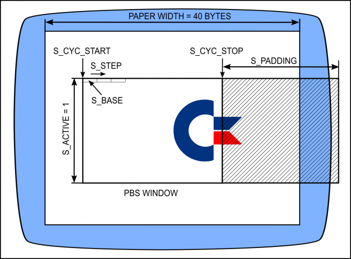
The image below depicts the role of PBS registers in a visual way, please read on for their detailed description.
First, for the PBS to take action, four conditions need to be met:
- Bit
DENof VIC-II register$d011needs to be set (which is normally the case if the display is on). - Bit
S_ACTIVEof VASYL registerPBS_CONTROL($40) needs to be set. - The current cycle in a rasterline has to be equal or larger than the contents of register
S_CYC_START. - …but smaller than the contents of register
S_CYC_STOP.
The first condition is normally met, so no point worrying about it.
As soon as S_ACTIVE is set, VASYL starts paying attention to the contents of S_CYC_START and S_CYC_STOP registers. Normally, after power up or reset these registers are set respectively to 15 and 55, values that correspond to the left and right edges of visible display area. In other words, by default, if S_ACTIVE is set, PBS overrides all forty memory accesses in any given display line. This is convenient, but by no means required - our window can be as narrow as a single cycle. For example, to approximate the configuration visible in the picture, we could set S_CYC_START to 15+5=20 and S_CYC_STOP to 55-12=43.
Once PBS decides to act, it performs following operations in every cycle:
- It uses an internal copy of
S_BASEregister to determine where to fetch graphics data from.S_BASEis a 16-bit register, so the addressable memory is 64KiB - one memory bank. Which of the eight memory banks is used is controlled by bitsS_RAMBANKin registerPBS_CONTROL($40:210). - Once graphics data byte is fetched, VASYL can do some simple bitwise operations on it (see below), then writes it to the VIC-II data bus.
- Finally, the internal copy of
S_BASEis incremented byS_STEP, yielding the address of a byte to use in the next cycle. With a typically organized graphics data, this value is equal to 1.
One cycle after the last active cycle in a rasterline, PBS does one more thing - it increases its internal copy of S_BASE by the value of register S_PADDING, yielding the memory address of the first byte of the next line. If our graphics data is laid out sequentially in memory (i.e. the last byte in a line is directly followed by the first byte of the next line), S_PADDING is going to be 0. But if you wanted to open a virtual screen larger than the display window, you would use S_PADDING to “skip over” the currently invisible (off-screen) part of the virtual display - as it happens to the rightmost part of C= logo in the illustration above.
Examples
CYC_START = 20
CYC_STOP  = 43
HEIGHT = 40
        MOV     VREG_PBS_PADDINGL, 0
        MOV     VREG_PBS_PADDINGH, 0
        MOV     VREG_PBS_STEPL, 0
        MOV     VREG_PBS_STEPH, 0
        MOV     VREG_PBS_CYCLE_START, CYC_START
        MOV     VREG_PBS_CYCLE_STOP, CYC_STOP
        WAIT    100, 0
        MOV     VREG_PBS_CONTROL, 1 << PBS_CONTROL_ACTIVE_BIT
        MOV     VREG_PBS_BASEL, <bitmap
        MOV     VREG_PBS_BASEH, >bitmap

        DELAYV  HEIGHT
        MOV     VREG_PBS_CONTROL, 0
        END

bitmap:
        .byte $ff
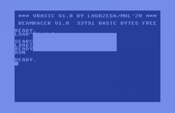
If you build and run this code, the screen should look as follows.
Note that we use 0 for step value, thus PBS repeatedly fetches the same byte - $ff. If you have VBASIC loaded, you can quickly inspect VASYL memory using VLIST 0 and see that “bitmap” starts at location $1a. Let's change it using VPOKE $1a, $aa or, even better
FOR I=0 TO 255: VPOKE $1a,I: NEXT
Now let's do a minor adjustment to our code:
CYC_START = 20
CYC_STOP  = 43
HEIGHT = 40
        MOV     VREG_PBS_PADDINGL, 1
        MOV     VREG_PBS_PADDINGH, 0
        MOV     VREG_PBS_STEPL, 0
        MOV     VREG_PBS_STEPH, 0
        MOV     VREG_PBS_CYCLE_START, CYC_START
        MOV     VREG_PBS_CYCLE_STOP, CYC_STOP
        WAIT    100, 0
        MOV     VREG_PBS_CONTROL, 1 << PBS_CONTROL_ACTIVE_BIT
        MOV     VREG_PBS_BASEL, <bitmap
        MOV     VREG_PBS_BASEH, >bitmap

        DELAYV  HEIGHT
        MOV     VREG_PBS_CONTROL, 0
        END

bitmap:
        .repeat HEIGHT, I
        .byte I
        .endrep
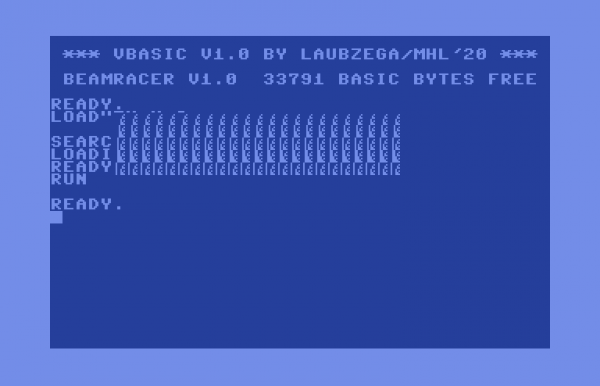
This time we advance the bitmap pointer by one at the end of every line. Given that this will cause a new byte to be used in each line, we also add some more data after the bitmap label. The result:
which shows the first line filled with byte 0, second with 1, and so on. These bytes are again located starting from location $1a, so feel free to VPOKE them some more.
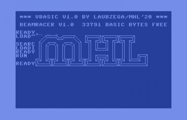
Let's now try using an actual image. You can find it in MadHackersLab GitHub repository. The code needs to be adjusted for its different size:
CYC_START = 20
CYC_STOP  = 49 ; the image is 29 bytes wide...
HEIGHT = 65    ; taller than the example block...
        MOV     VREG_PBS_PADDINGL, 0 ; ...and is sequentially laid out in memory
        MOV     VREG_PBS_PADDINGH, 0
        MOV     VREG_PBS_STEPL, 1
        MOV     VREG_PBS_STEPH, 0
        MOV     VREG_PBS_CYCLE_START, CYC_START
        MOV     VREG_PBS_CYCLE_STOP, CYC_STOP
        WAIT    100, 0
        MOV     VREG_PBS_CONTROL, 1 << PBS_CONTROL_ACTIVE_BIT
        MOV     VREG_PBS_BASEL, <bitmap
        MOV     VREG_PBS_BASEH, >bitmap

        DELAYV  HEIGHT
        MOV     VREG_PBS_CONTROL, 0
        END

bitmap:
        .include "mhl.xbm"
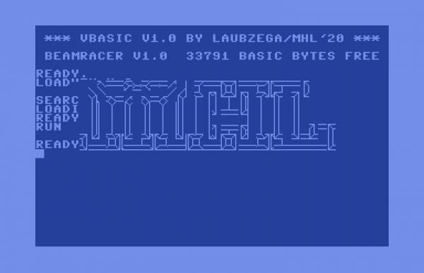
Here is the result…
Ouch! What happened here? Closer inspection reveals that the order of bits in each byte seems reversed. This is because VIC uses MSB to LSB bit order when shifting out pixels from bytes PBS gives it, i.e. it first uses bit 7, then 6, then 5, and so on until bit 0 gets to the screen. However, the file format the MHL image was saved in uses LSB to MSB bit order. This could naturally by trivially fixed by inverting the bit ordering in the file. But why bother, if we have hardware to do that for us? Let's change PBS settings as follows:
CYC_START = 20
CYC_STOP  = 49 ; the image is 29 bytes wide...
HEIGHT = 65    ; taller than the example block...
        MOV     VREG_PBS_PADDINGL, 0 ; ...and is sequentially laid out in memory
        MOV     VREG_PBS_PADDINGH, 0
        MOV     VREG_PBS_STEPL, 1
        MOV     VREG_PBS_STEPH, 0
        MOV     VREG_PBS_CYCLE_START, CYC_START
        MOV     VREG_PBS_CYCLE_STOP, CYC_STOP
        WAIT    100, 0
        MOV     VREG_PBS_CONTROL, 1 << PBS_CONTROL_ACTIVE_BIT | PBS_CONTROL_SWIZZLE_MIRROR
        MOV     VREG_PBS_BASEL, <bitmap
        MOV     VREG_PBS_BASEH, >bitmap

        DELAYV  HEIGHT
        MOV     VREG_PBS_CONTROL, 0
        END

bitmap:
        .include "mhl.xbm"
and VASYL will automatically flip (“mirror”) every byte before passing it to VIC-II. Here's the final result:
Bonus stage. ;) With the above image on screen execute the following one-liner.
FOR I=0 TO 99 STEP .1: VPOKE $D, SIN(I)*60+120: NEXT
Hint: location $d in VASYL memory stores the vertical argument of the WAIT instruction.

