Table of Contents
Introduction to BeamRacer Programming
Overview
Producing non-trivial visual effects on Commodore 64 requires tight cooperation between main CPU and VIC-II: as VIC-II is generating video image, the 6510 waits for the electron beam sweeping the screen to reach a specific location, and then immediately writes to one or more VIC-II registers, changing colors, graphic modes, video banks, or perhaps affecting the chip’s internal circuitry to make it behave in ways unforeseen even by its designers.
The downside of this is quite obvious - 6510 spends at least some time doing nothing but waiting for the right moment(s) to nudge the VIC-II. This can be partially mitigated with the help of interrupts, but high precision required by many advanced effects means that the CPU is otherwise unavailable for a significant portion of the video frame.
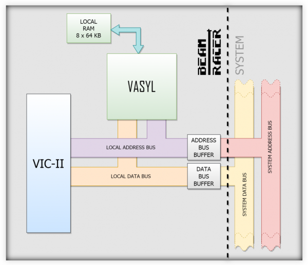
BeamRacer lifts this responsibility from 6510’s shoulders, offering a dedicated coprocessor called VASYL (Video Assistance and Support Logic), which can be programmed to do exactly what’s needed at exactly the right time in the video frame. Together with accompanying logic chips on the BeamRacer board, VASYL can not only completely take over communication towards VIC-II, but also do this while working outside of C64’s system bus, becoming in many ways transparent to other system components.
While simple effects can be implemented relatively quickly and with minimal programming, full depth of the board’s capabilities can only be properly realized with careful study of this manual and the accompanying examples.
What is VASYL
VASYL is the core logic chip on the BeamRacer board, incarnated inside Altera MAX-II EPM1270. Working in synchrony with VIC-II, it controls various auxiliary chips and executes software programs (so-called display lists) that define what’s going to happen at particular times in a video frame. VASYL fetches display list instructions from a local memory at a maximum rate of one per system clock cycle. Some of these instructions only affect VASYL’s internal state, some have an impact on VIC-II or 6510. With careful programming, VASYL can also be made to write its own display lists, further offloading the main CPU.
Initialization
In order to maintain a high level of compatibility with existing C64 software, BeamRacer remains hidden on power up, and the computer behaves as if it was not there. That is, register writes are ignored, and reads report the same values as those in a vanilla C64. It is necessary to perform so-called “register knocking” for the board to reveal its presence. This is achieved by writing a sequence $42, $52 (screen codes for “BR”) to register $D031. To check if the board is indeed there, register $D031 can then be read and verified. Value of $FF means that BeamRacer was NOT activated.1)
VREG_CONTROL = $D031

	LDX VREG_CONTROL
	INX
	BNE BEAMRACER_ALREADY_ACTIVE
	LDX #$42
	STX VREG_CONTROL
	LDX #$52
	STX VREG_CONTROL
	LDX VREG_CONTROL
	INX
	BNE BEAMRACER_FOUND_AND_ACTIVATED
	RTS 	; sadly, no BeamRacer...
Local Memory
For VASYL to execute a display list, it first needs to be placed in its local memory (LRAM). BeamRacer provides VASYL with eight banks of 64KiB of LRAM each. The 6510 can put data into LRAM using two one-byte wide ports. Each port is built out of five registers:
ADRL/ADRH are respectively the LO and HI bytes of a 16-bit address in a LRAM memory bank. Together they determine the location where data will be written to (or read from), while register PORT is used to transfer the actual value. A following code
	LDA #$06
	STA VREG_ADR0L	; we use the first of the two ports, hence 0 in the name
	LDA #$01
	STA VREG_ADR0H
	LDA #$FF
	STA VREG_PORT0
will store value $FF into memory location $0106 of a currently selected LRAM bank. Since using that many instructions per transferred byte would be very inefficient, register STEP can be used to automatically move the destination pointer: its content (an 8-bit signed value, i.e. [-128,127]) is added to ADRL/ADRH after every transfer. A following loop copies 256 bytes to successive locations starting at LRAM address $2000:
	LDA #$00
	STA VREG_ADR0L
	LDA #$20
	STA VREG_ADR0H
	LDA #$01	; advance LRAM pointer by one after every transfer
	STA VREG_STEP0
	LDX #0
loop:
	LDA data,X
	STA VREG_PORT0
	INX
	BNE loop
On some occasions you may also want to read from LRAM with the CPU. There is an extra step involved, as many 6510 addressing modes result in a bus READ access before the requested WRITE occurs, which could lead to confusing results if not used with care. Register CONTROL has a bit named PORT_READ_ENABLE, which is used to enable reading from both ports. To read every 4th byte of a 256-byte long sequence starting from LRAM location 0, the following code would be used
	LDA VREG_CONTROL
	ORA #CTRL_PORT_READ_ENABLE
	STA VREG_CONTROL

	LDA #$00
	STA VREG_ADR0L
	STA VREG_ADR0H
	LDA #$04
	STA VREG_STEP0
	LDX #0
loop:
	LDA VREG_PORT0
	STA DATA,X
	INX
	CPX #256/4
	BNE loop
Note:
- Registers ADRL/ADRH can be read to inspect the current value of LRAM pointer.
- Reading from LRAM is rarely useful, only enabling it when needed and then disabling it back will help avoid “weird” problems.
- The two ports are fully independent of each other - they can point to different locations, advance with different STEPs and operate in different directions.
First Instructions
VASYL instruction set has been designed to be short yet versatile, and contains opcodes for video beam synchronization, data transfer, bad line forcing, flow control and others. Each instruction is one or two bytes long and requires one system clock cycle to fetch and start executing. Most instructions finish processing in the same cycle, but ones used for waiting will naturally take more time.
Let's start with something simple.
WAIT and MOV
These are the two most useful instructions. WAIT makes VASYL stop executing its program and wait until the video beam reaches the position specified as WAIT’s arguments.
WAIT 30,60
will thus pause execution until the beam gets to the 60th cycle in the 30th rasterline. The simplest complete display list is
WAIT 511,63
which will make VASYL wait indefinitely, as line 511 is never reached - neither in PAL, nor in NTSC. Note that if the video beam is already past the position specified by WAIT’s arguments, there will be no pause and instruction processing will continue in the next cycle. Therefore in this sequence
    WAIT 100,30
    WAIT  20, 0
the second instruction will be ignored and act as a NOP (no-operation).
MOV is an instruction used to transfer a value to a VIC-II or VASYL register. The first argument is the number of the destination register (where 0 corresponds to $D000 in regular memory space), while the second argument is a byte value to be stored in the register. For example
MOV $20,0
will set register $D020 to 0 (and thus make the border color black).
This is enough knowledge to write our first useful display list.
    WAIT  48,13
    MOV	 $20, 1
    MOV	 $20, 2
    MOV	 $20, 3
    MOV	 $20, 0
    END         ; this is a handy alias for instruction "WAIT 511,63"
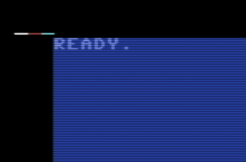
which should produce the following result in the top-left corner of the screen.

DELAYV and DELAYH
In some situations it is more convenient to use relative, rather than absolute positioning on the screen. For example, consider a display list that creates a small rasterbar.
    WAIT  48, 0
    MOV	 $20,15
    WAIT  49, 0
    MOV	 $20, 1
    WAIT  50, 0
    MOV	 $20,15
    END
Moving the bar up and down would require adjusting arguments of all WAIT instructions. Instead, we can use “DELAYV n” instruction, which makes VASYL wait until the beginning of the line “n” lines down from the current one. So “DELAYV 1” waits for the beginning of the next line, “DELAYV 2” for the one after that, and so on. A special case is “DELAYV 0”, because waiting for the beginning of the current line does not make much sense. It will thus just act as a NOP.
Below is the display list modified to use DELAYV instruction. To move the rasterbar now, only the first WAIT’s arguments need to be changed.
    WAIT    48, 0	; starting line
    MOV	   $20,15
    DELAYV   1
    MOV	   $20, 1
    DELAYV   1
    MOV	   $20,15
    END
An equivalent instruction for introducing horizontal delay is “DELAYH n”, which stops the display list’s execution for “n” CPU cycles.
BRA
If you ever need to repeatedly execute a part of a display list, or perhaps want to skip over some code, “BRA offset” instruction comes handy. “Offset” is a signed value ranging from -128 to 127 that determines in which direction and by how many bytes – counting from the first byte of the following instruction – to jump.
BRA 10
will thus skip the ten bytes immediately following the instruction and its argument.
Some more examples follow.
    BRA -20    ; Jump 20 bytes back
    BRA 0      ; This does nothing, we skip 0 bytes and execute
               ; the next instruction normally.
    BRA -2     ; We skip back to ourselves. Hello, Infinite Loop!
Let's now combine BRA with the rasterbar from previous section for something more practical.
    WAIT    48, 0	; starting line
loop:
    MOV	   $20,8
    DELAYV   1
    MOV	   $20, 1
    DELAYV   1
    MOV	   $20,8
    DELAYV   1
    MOV    $20, 0
    DELAYV  10          ; a larger gap between individual rasterbars
    BRA    loop         ; loop endlessly
    END                 ; never reached
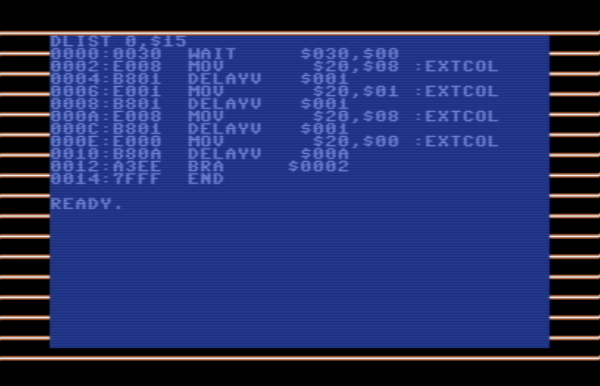
When you execute it, the border should look like in the image below.
Note that although our exercise resulted in an infinite loop (BRA is always jumping back), no crash or hang occurs - the computer operates perfectly fine and not a bit slower. This is because at the end of every frame the execution of display list is aborted, and then immediately restarted from the beginning (as defined by registers DLIST(LH)).
While this nice feature of VASYL makes infinite loops practical, in many situations we want to have more control over the number of loop repetitions. Let's close this intro chapter with two more instructions useful for exactly that.
SET and DEC
VASYL contains two internal 8-bit counters called A and B, which are intended to make controlled looping easy. This is how it works.
Instruction “SETA N” loads value N (ranging from 0 to 255) to counter A. Instruction “SETB N” does the same for counter B. For instance
    SETA   3        ; set counter A to 3
    SETB 255        ; set counter B to 255
To make a counter run, we now need to use instruction “DECA” for counter A, or “DECB” for counter B. What it does is a bit more complicated - first, it checks if the value held by respective counter is equal to “0”, and if it is, it skips the next two bytes of the display list (which usually is how much space the next instruction occupies). If the value in the counter is anything else than zero, the instruction decrements it by one, and then continues normally.
This is best illustrated building on the previous example, with newly added lines highlighted.
    WAIT    48, 0	; starting line
    SETA     3          ; load 3 to counter 0
loop:
    MOV	   $20, 8
    DELAYV   1
    MOV	   $20, 1
    DELAYV   1
    MOV	   $20,8
    DELAYV   1
    MOV    $20, 0
    DELAYV  10          ; a larger gap between individual rasterbars
    DECA                ; zero? skip the next instruction. not zero? decrement
    BRA    loop         ; will be skipped when counter 0 reaches 0
    END
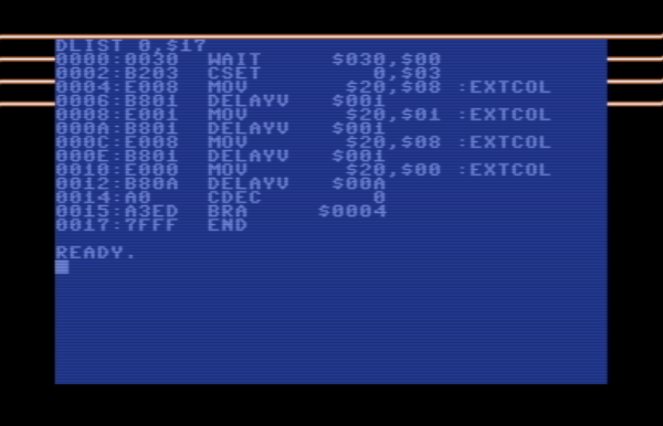
The result this time looks as follows.
What happened here? On the first iteration through the loop, the counter A holds value 3. This is clearly different from 0, so all DECA does is to decrement it by one. On the next iteration (when the second rasterbar is drawn) it holds value 2. On the third (third rasterbar) - the value is 1. Finally, on the fourth iteration (fourth rasterbar), the counter A holds the value of 0. When we get to execute DECA this time, it does things differently. Since counter A has ran out, DECA skips the next instruction (BRA). Display list then reaches instruction END, which makes sure that nothing more happens in this frame. And the next frame, the whole cycle repeats, since SETA reinitializes the counter to 3.
A good thing about having two counters is that they can be used to construct nested loops. How about drawing three groups of four rasterbars each, where space between groups is twice the size of space between individual bars? Please give it a try!
Finally, be aware that when DECA or DECB decides to skip, it has no idea how many bytes the next instruction occupies - one or two - so it always skips two. Instructions used for jumping (of which BRA is one example) take two bytes, so this fits nicely. But once you start composing more advanced display lists and discover other uses for DEC instructions, be sure to verify the number of bytes used by the next instruction (in this table), and if happens to take just a single byte, simply pad it with a NOP.
This concludes our introduction to BeamRacer programming. Please practice what you have learned here before moving on to the next chapter.


