

beamracer_installation
This is an old revision of the document!
Table of Contents
Preparation
While BeamRacer installation is a relatively easy task, requiring neither specialised skills nor equipment, a few preparation steps need to be taken in order to properly conduct the process. The assumption is that the person performing the installation does not have access to a specialised electronic workplace but is still comfortable with using common household tools.
Please read this document in full before proceeding with the installation - it's always better to know what lies ahead.
NOTE: When installing, we strongly suggest following the order presented in this document:
- Retrieve the VIC and place it on the BeamRacer board
- Install the riser socket on the other side (if installing in the “breadbin” C64)
- Install the whole unit with both VIC and socket (if socket used) on the mainboard
Tools
Since you don't have access to professional electronic workshop and tools1) you are going to need:
- Clean, flat table surface, of about ten square feet / one square metre
- Phillips PH1 and PH2, screwdrivers2)
- Relatively thin yet wide flat screwdriver
- Saucer for holding small screws
In some cases of computer mainboard and casing combinations you may also need:
- a soldering iron suitable for soldering electronic components (temperature controlled!) with approximately 50W to 100W of power
ESD Precautions
We are going to work with static electricity sensitive devices. This means that you need to be well accustomed with the best practices and guidelines on avoiding potentially damaging electrostatic discharges. A good description and set of guidelines can be found e. g. on this "wikiHow" page.
Preparing the computer
The following needs to be done before the installation
- Full check that the computer is still fully operational. This is especially important if you haven't used it for some time
- Opening the computer case so that unrestricted access to its mainboard is available
- Removal of the laminated paper shield or metal shield cover
- Final, pre-installation check that the machine still powers up without problems
If you are not familiar with the innards of your Commodore 64, we shall try to provide you more thorough instructions on the Computer Preparation page
Removing VIC-II from the mainboard
The VIC-II chip needs to be removed from the computer's mainboard before it is installed on the BeamRacer. Since all known variants of Commodore 64 mainboard come with VIC-II installed in an IC socket, there is no need for any soldering. Still, the removal has to be done carefully to avoid any possible damage
Obtaining access
On all older, “wide” boards VIC-II is not readily available after opening the computer case. It can be either closed inside a metal “can” with a specialised lid or covered with metal shielding plate. These have to be removed before the chip can be accessed for removal. Check the "wide" boards page for pictures of this family of boards with VIC-II exposed
On the newer, "narrow" boards the access is not restricted in any way.
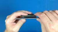
Placing VIC-II on the BeamRacer board
Your VIC-II integrated circuit, which you just removed from your computer, needs to find its way onto the BeamRacer. Therefore
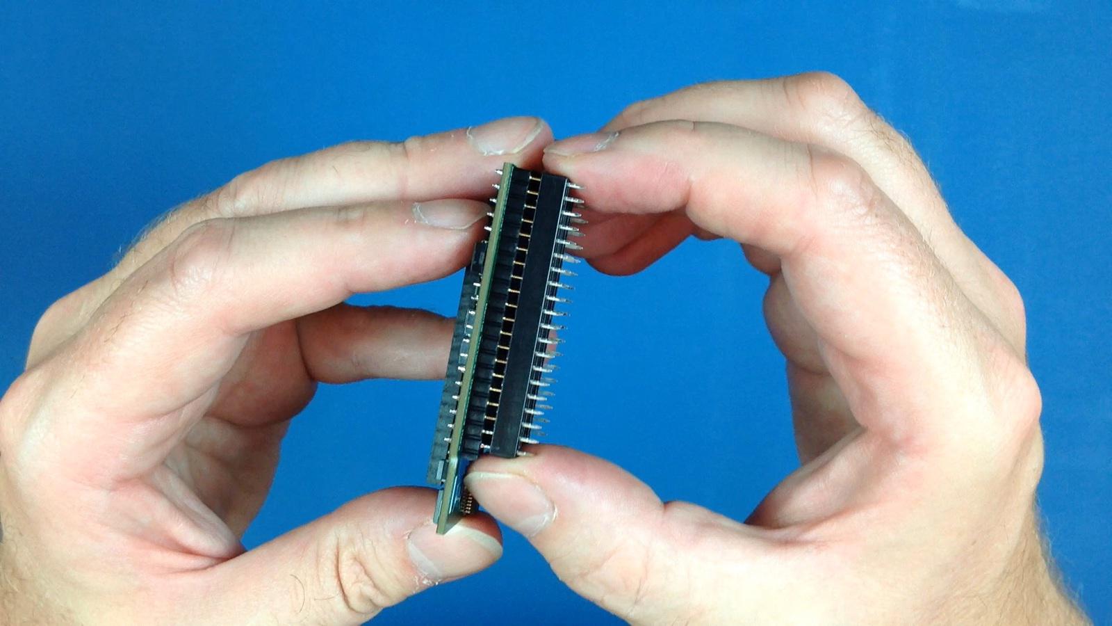
- Locate orientation notches on both the VIC-II and the BeamRacer socket
- Make all of the chip's pins find their clean way into the socket's openings. Do not push them fully in yet!
- Once all pins sit clearly inside their respective holes press gently both sides together with two thumbs and fingers placed symmetrically around the centre
§
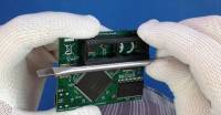
Installing riser socket
All “wide” Commodore 64 boards require that you place the rising and protective socket on the pins sticking out from the bottom of the BeamRacer board. This additional socket not only keeps the BeamRacer unit safely above the computer's mainboard but is also especially chosen to have flat pins, rather than round ones. Thanks to this no additional wear is imposed onto your original VIC-II socket when the expansion is installed.
NOTE: If your compouter's mainboard is one of the "narrow" ones AND your computer case is of the newer, “flat” type – the Commodore 64C units fall into this category – you may elect not to install the riser socket and follow the C64C specific installation procedure instead
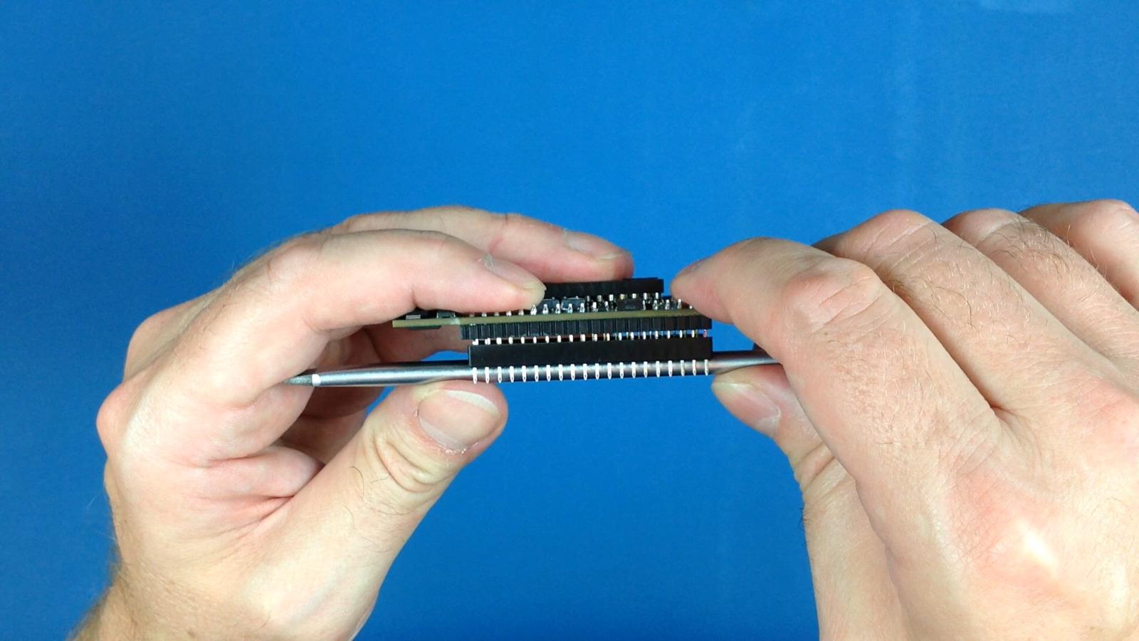
- Check and align orientation notches on both the BeamRacer top socket and the riser socket
- Make sure that all the downward facing BeamRacer board pins fit well inside the riser socket openings
 Align the socket pins to form a straight line with the BeamRacer board pins. There is a bit of play so it is important keep the two aligned against each other
- Double check that all pins fit with no bend-ins or bend-outs
 Press gently but firmly the two together using a stiff straight object. It is OK to do it one side at a time. Be prepared to apply considerable amount of force (it has to sit very firmly) but re-check everything if you feel like an excessive force is already at play!
- Make sure that there are no gaps left either of both sides
 Re-check that no socket pins were bent. Straighten gently if any of them got misplaced
Your BeamRacer is now ready to be installed.
Installing prepared BeamRacer board
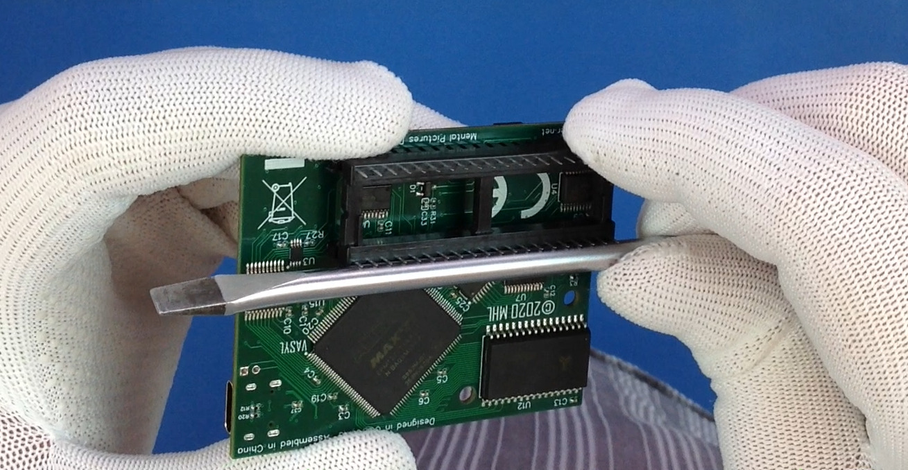
- Locate the orientation notches on both the VIC-II chip and the original socket on the mainboard3). In all known cases this should be either on the left-hand side or at the far side, when the mainboard is placed in its normal, working orientation with connectors away from you and to the right
- Align orientation notches on the VIC-II/BeamRacer and the mainboard the same way
- Double-check that all pins are still completely straight! Adjust gently if necessary
- Place the prepared BeamRacer board with its pins facing downward carefully on top of the original VIC-II socket, making sure that every single pin finds its way into respective original socket's opening
- Press the whole BeamRacer unit gently, using two fingers, down. It should slide smoothly in, requiring no sizeable force but must also not simple “fall in”, requiring almost no force4). Recheck everything if that's not the case
VERY IMPORTANT – The two sockets MUST be 100% aligned. Inserting the BeamRacer unit misaligned can cause irreparable damage to your computer and/or BeamRacer!
Testing installation
NOTE: Before connecting power supply back to your computer recheck the installed BeamRacer board for any misalignment / visible pins. Proceed only if none found.
- Check that the power switch is in its
OFFposition. Correct otherwise - Connect your monitor and power supply
- Turn on the monitor
- Looking at the BeamRacer board from above turn on the computer
The red “POWER” led should light up immediately, shortly followed by a green “AUTOCONFIG OK”, and finally red “INACTIVE”. Once that happens, the venerable startup screen of your Commodore 64 should appear on the monitor.
NOTE: If you don't see the red LED light right after turning the machine on, turn it back off immediately (!) and follow the checklist in the troubleshooting section
Closing the computer
All older, “breadbin” type of Commodore 64 casings should have no problems closing them after BeamRacer installation. The newer, “flat” casings of Commodore 64C should close correctly if the C64C installation procedure was followed.
Troubleshooting
As all BeamRacer units are fully tested for function before packing, there is virtually no chances (mechanical damage in transport excluding) of you receiving them DOA. If any of the following symptoms occur
- No LEDs activity on the BeamRacer board
- Not all three BeamRacer LEDs are lit
- No startup screen
- Demo programs don't work as expected
the most probable cause will be an installation related issue. First and foremost turn the machine OFF as soon as you notice the symptoms. Then
- Pull gently up and remove the BeamRacer out of your computer
- The unit should not be too easy to remove. If it requires close to zero force to remove the board - that's a warning sign. Typical reason for such loose fit is the original socket's fatigue. In such case you may be able to temporarily work the symptoms around by using a round pinned riser socket instead of the supplied flat pinned one. Still, even if this works short-term, we suggest replacing your original VIC-II socket by a well trained technician
- The riser socket should not separate itself from the BeamRacer. If it does, the reason for this needs to be found. Most probably the riser socket was not correctly installed before proceeding with the actual installation
- Verify all the downward facing pins. None of them should exhibit any signs of deformation
- Check whether the orientation notches on the mainboard and BeamRacer were pointing the same direction
- Check whether the orientation notches on the VIC-II integrated circuit and the BeamRacer socket are facing the same direction
If none of the above yields any discovery/ies
- Check your power supply
- Connect computer upper casing's LED cable to its mainboard header then turn the power back on and check if the casing LED starts emitting light5)
- Check the fuse on the mainboard and replace if blown. Make sure you replace it with exactly the same type and rating!
1)
Obviously if you do, then you also know (or know someone who knows) how to use them
2)
Depending on your particular Commodore 64 unit, only one of the two may be needed
3)
In case the orientation notch is not present on the original socket, check the white outline drawing on the board itself - it should be partially visible below the socket
4)
In such case, your original VIC-II socket is most probably showing signs of fatigue already. Unreliable connections and system instability will develop sooner or later. See the Troubleshooting section for suggestions
5)
VIC-II does not necessarily have to be reinstalled for this quick test
beamracer_installation.1601483397.txt.gz · Last modified: 2020/09/30 09:29 by silverdr